Katana Switch GUIDE
The Katana device includes an inbuilt PoE Layer 2 switch that can be configured through a web-based interface. It is important to note that Katana and the inbuilt Katana switch are two separate components, each with its own network configuration.
The inbuilt switch allows you to perform tasks such as assigning static IP addresses, configuring a DHCP server, and power-cycling PoE ports to restart connected cameras. To access and manage the switch, your computer must be configured on the same subnet as the switch’s default IP address.
Katana LAN Connection & Network Setup
The Katana device and the inbuilt PoE switch are two separate components. The inbuilt switch has its own IP configuration and can only be accessed when katana is on the same subnet.
To communicate with the Katana switch, you must assign an IP address to Katana’s LAN interface that belongs to the same subnet as the switch.
Important: An Ethernet cable must be connected to the LAN port of the Katana device. Without a LAN connection, the inbuilt switch will not be accessible.
Refer to the images below for the LAN port location on both 8-Port and 16-Port Katana switches:
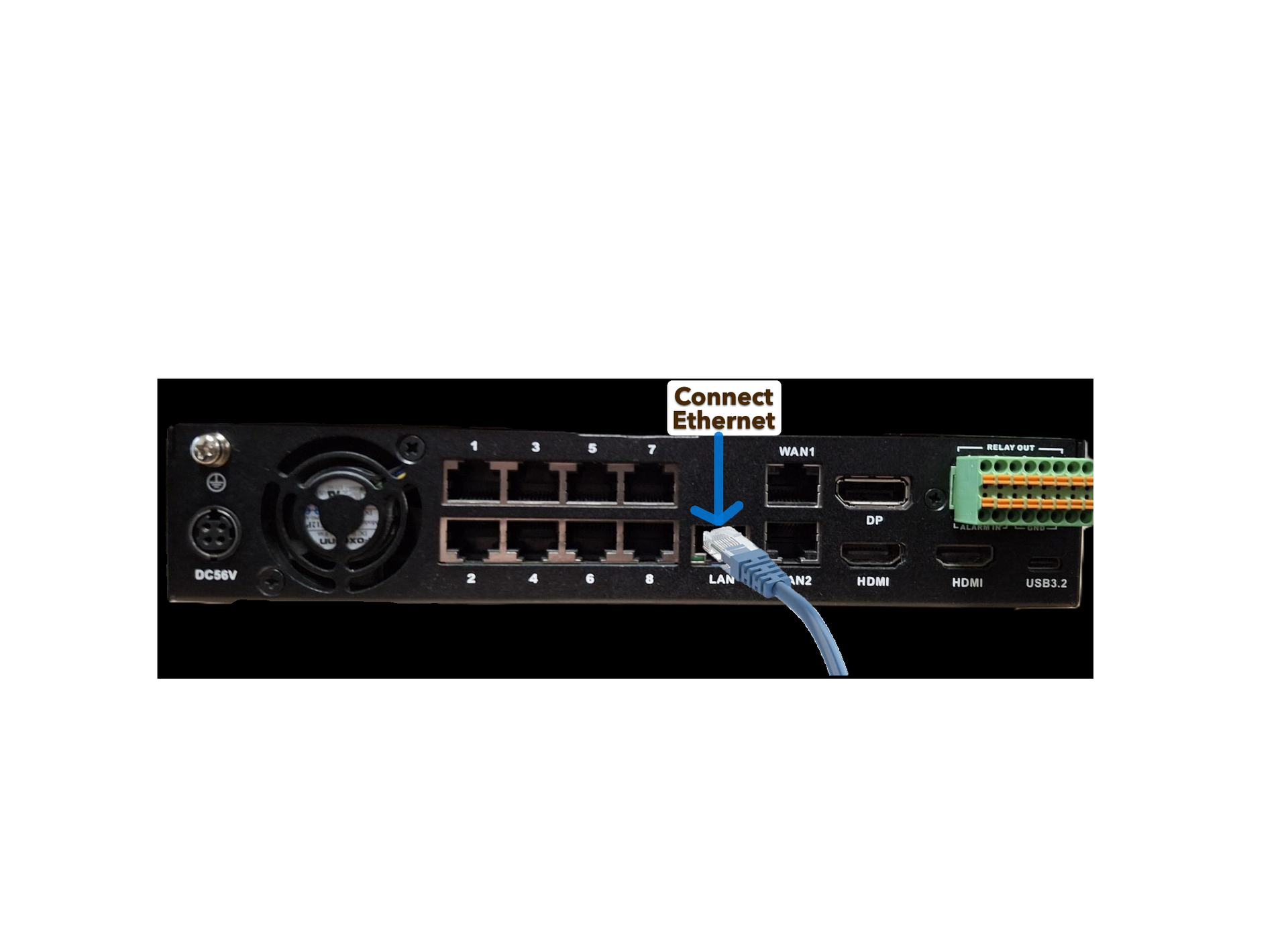
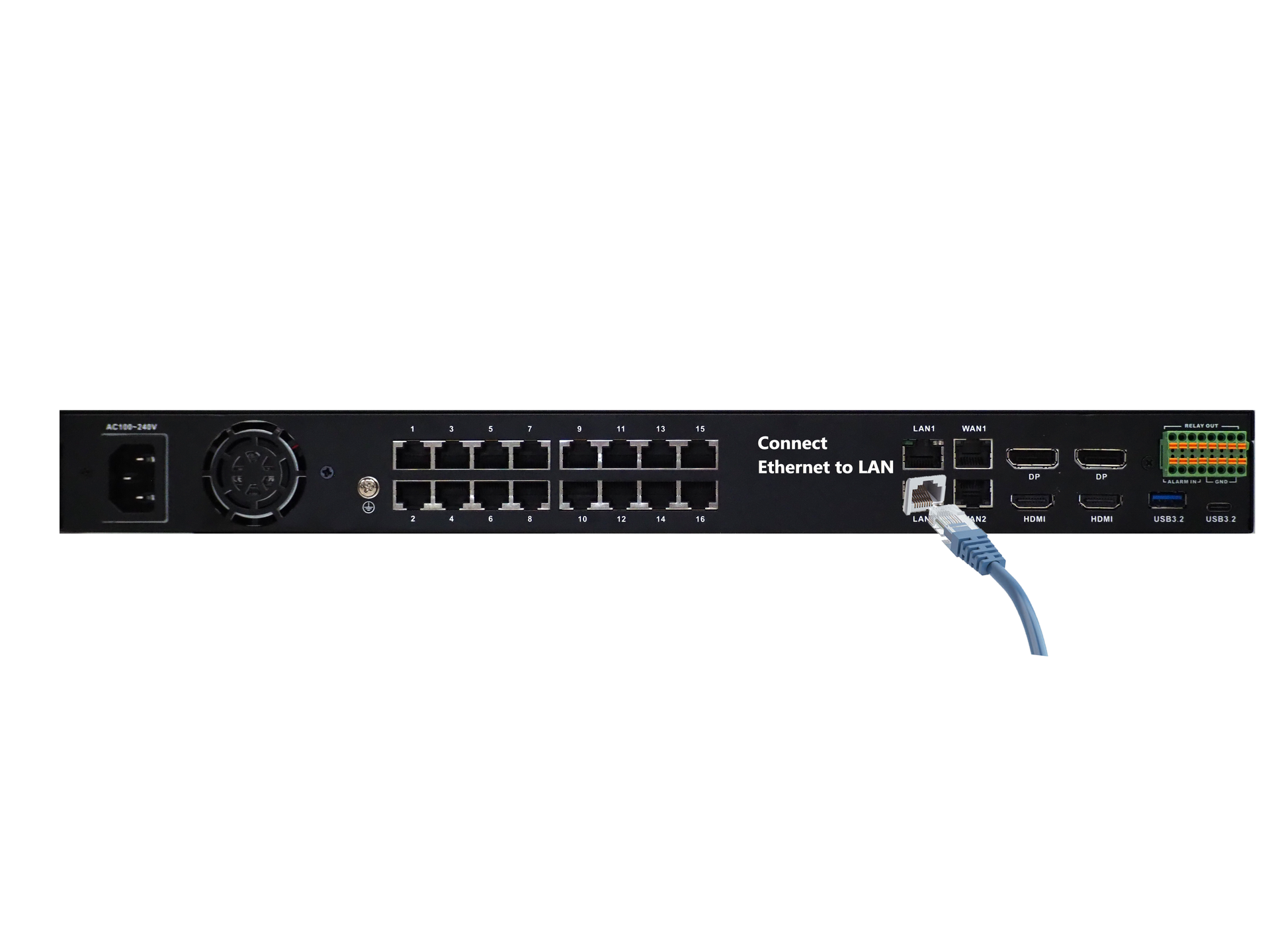
Katana 8-Port LAN Port Katana 16-Port LAN Port
Common Network Scenarios
Scenario 1: Corporate Network + CCTV Network
- Connect the CCTV network to the LAN port
- Connect the corporate network to the WAN port
- Use the WAN port for internet access
- Use the LAN port exclusively for the CCTV network
Scenario 2: No Separate Corporate Network
If there is no separate corporate and CCTV network, connect your network directly to the LAN port.
Scenario 3: Standalone 4G Router
When using a standalone 4G router, ensure the router is configured with the correct:
- Subnet
- Subnet Mask
- Default Gateway
- DNS Server
Example:
If your CCTV network is 192.168.4.0/24 and your 4G router IP is 192.168.4.1, then the gateway for all devices on that network should be 192.168.4.1.
Important: Network examples in this guide are for reference only. Always verify your actual network configuration before applying any settings. Do not rely solely on images or example IP addresses.
KATANA – Katana Inbuilt Switch Setup
This guide explains how to use the Katana Switch to manage network and camera configurations. It applies to both 8-Port and 16-Port models.
You can use the switch to create a separate network, assign static IP addresses, or configure settings such as PoE and port cycling.
A temporary IP address may be used to access the switch’s web GUI and perform the required configurations.
Step 1 – Set Temporary IP
First we need to set static IP for Katana so we can communicate with the inbuilt switch. By default, the switch IP is in the range 192.168.50.xxx/24 with its IP address being 192.168.50.17/24.
Make sure Ethernet is connected to LAN PORT of Katana switch before proceeding further.
Now we will set a temporary IP on Katana network interface to be in the same subnet as the Katana switch. For this enter value other than 17 for xxx in the command below and click Copy button to copy the command to clipboard. Press Ctrl+Alt+T keyboard shortcut to open terminal.
Use the following command template to set a temporary IP address :
Enter value for xxx (2–255, except 17):
sudo ip addr add 192.168.50.xxx/24 dev enp0s31f6
Step 2 – Access the Switch Webpage
Once temporary Ip is assigned to katana to the same network as the Katana switch. Open a web browser and enter the switch’s IP address: http://192.168.50.17.
Log in using the default credentials: Username: admin, Password: admin.
Tip: Make sure the Katana switch has been assigned a temporary IP before accessing the webpage.
Please refer to the images below for reference:
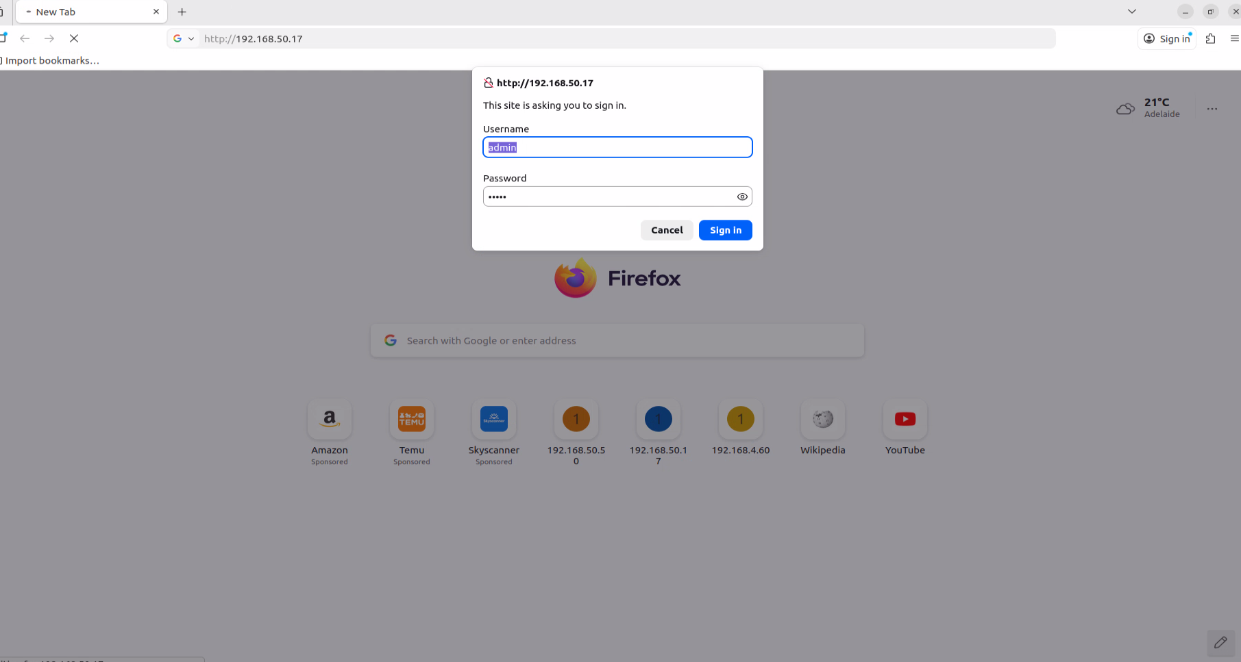
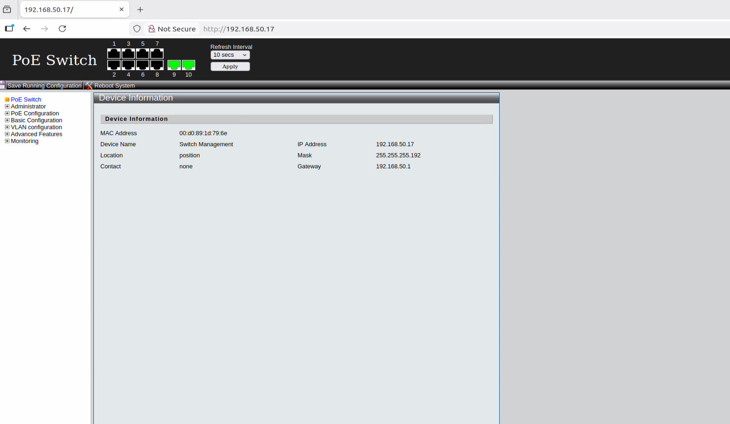
Switch Webpage Switch Dashboard
Step 3 – Configure Switch IP
In the switch web GUI, navigate to Administrator → IP Configuration → IPv4. Change the default static IPv4 address, Subnet Mask, Default Gateway, and DNS server according to your network requirements and the CCTV network the Katana switch is connected to via the LAN port.
Ensure that the new subnet is accessible from the Katana switch. Example: If the default static IP was 192.168.50.17, it can be changed to 192.168.4.2, and the Subnet Mask, Default Gateway, and DNS server should be updated based on your network configuration.
After making the changes, click Apply to save the configuration.
Important: Do not set the switch IP to DHCP. Using DHCP is not recommended and can cause connectivity issues.
Refer to the images below for guidance:
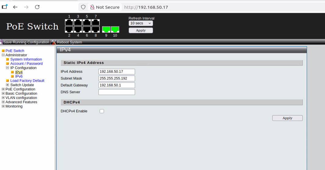
Static IP
→
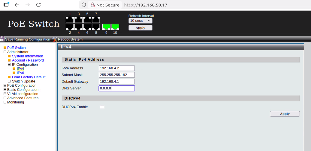
Change Static IP
→
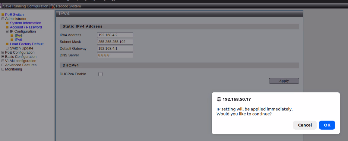
Confirm Change
Once the configuration is applied, open a web browser and access the switch using the newly configured IPv4 address. The login credentials will remain the same: Username: admin, Password: admin.
Please Click on Save Running Configuration button on top Left side to save the settings.
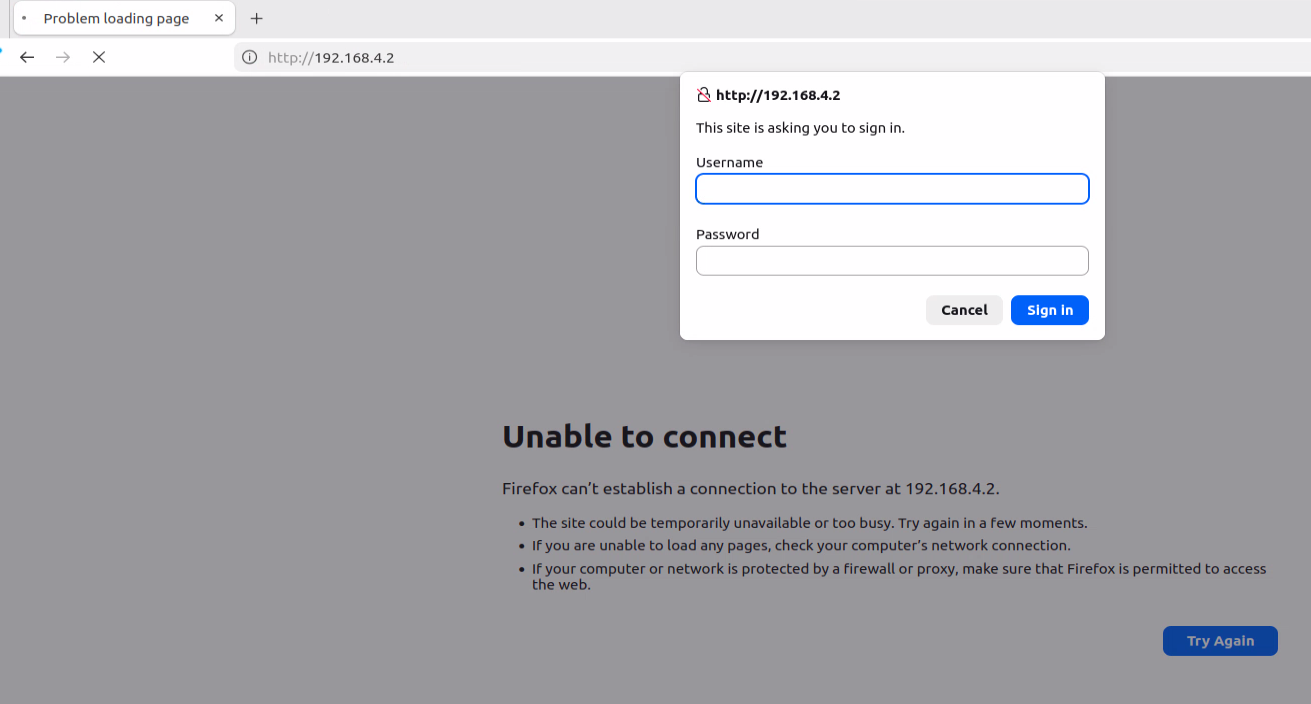
Open Webpage With New IP
→
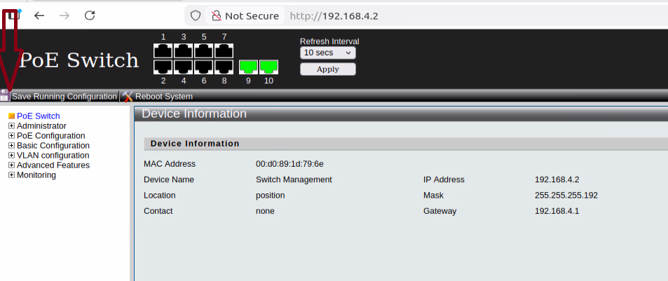
Dashboard
→
Save Configuration
Note: Assign a temporary IP to your computer if required. Use the following command and replace xxx with a value in the same subnet as the switch IP you configured:
sudo ip addr add (X.X.X.X/X) dev enp0s31f6
Step 4 – Configure Port IPs
DHCP Server Enabled with IP Range
Navigate in the switch web GUI: Advanced Features → DHCP Server.
By default, IPs are assigned sequentially starting from 192.168.50.21 up to the number of available ports. You can change this to match your required subnet. Example: changing it to 192.168.4.21 means IP range will be from 192.168.4.21 to 28 or 36 (8 port or 16-Port). So, camera connected to a particular port will receive that specific IP.
It is recommended to have the DHCP server running on the switch. This allows any camera connected to any port to automatically receive an IP if the camera is set to DHCP. If a camera is set to a static IP on a different subnet, it may need to be reset before it can connect properly.
For better network management, it is best to assign each camera the same static IP as what the switch would provide via DHCP. This makes it easier to track cameras and ensures consistent connectivity.
Note: Assign the DHCP IP range carefully according to your network, and ensure that all cameras either follow the DHCP assignment or are set with matching static IPs for consistent tracking. Avoid IP conflicts by ensuring no two devices share the same IP address.
Refer to the images below for guidance:
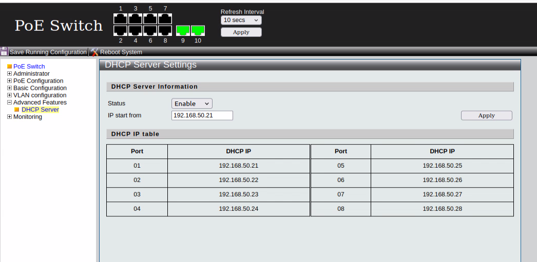
DHCP Default IP Start
→
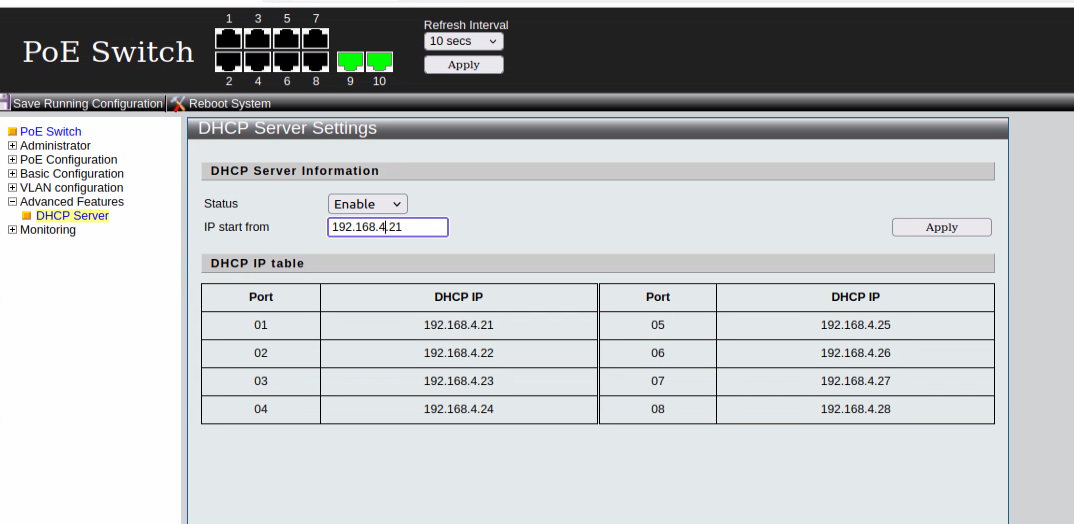
DHCP IP Start Changed
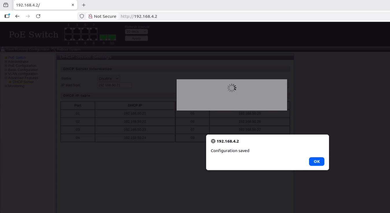
Disabling DHCP
If you want to disable DHCP, navigate to the Status dropdown menu in the switch web GUI and select Disable. After making the selection, click Apply to save the changes.
Please Click on Save Running Configuration button on top Left side to save the settings.
Note: Disabling DHCP means that cameras connected to the switch will not automatically receive IP addresses. Ensure that all connected devices have static IPs configured within the same subnet as the switch to maintain connectivity.
Refer to the images below for guidance:
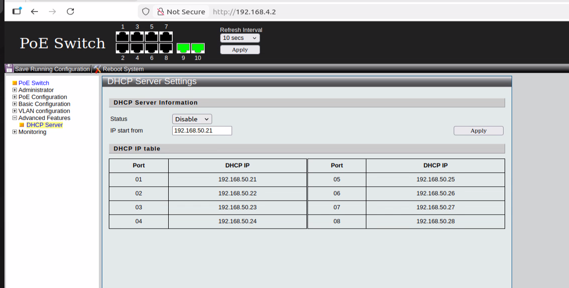
DHCP Default Status
Step 5 – Port Cycling
To manage PoE and power cycle ports on the Katana switch, follow these steps in the web GUI:
Navigate to PoE Configuration → PoE setting.
To Power Off a Port: 1. Select the ports you want to power cycle. 2. In the State dropdown menu, select Disable. 3. Set Priority from Low to Critical, as required. 4. Click Apply to execute the changes.
To Power On a Port: 1. Select the ports you want to enable. 2. In the State dropdown menu, select Enable. 3. Set Priority from Low to Critical, as required. 4. Click Apply to execute the changes.
Refer to the images below for guidance:
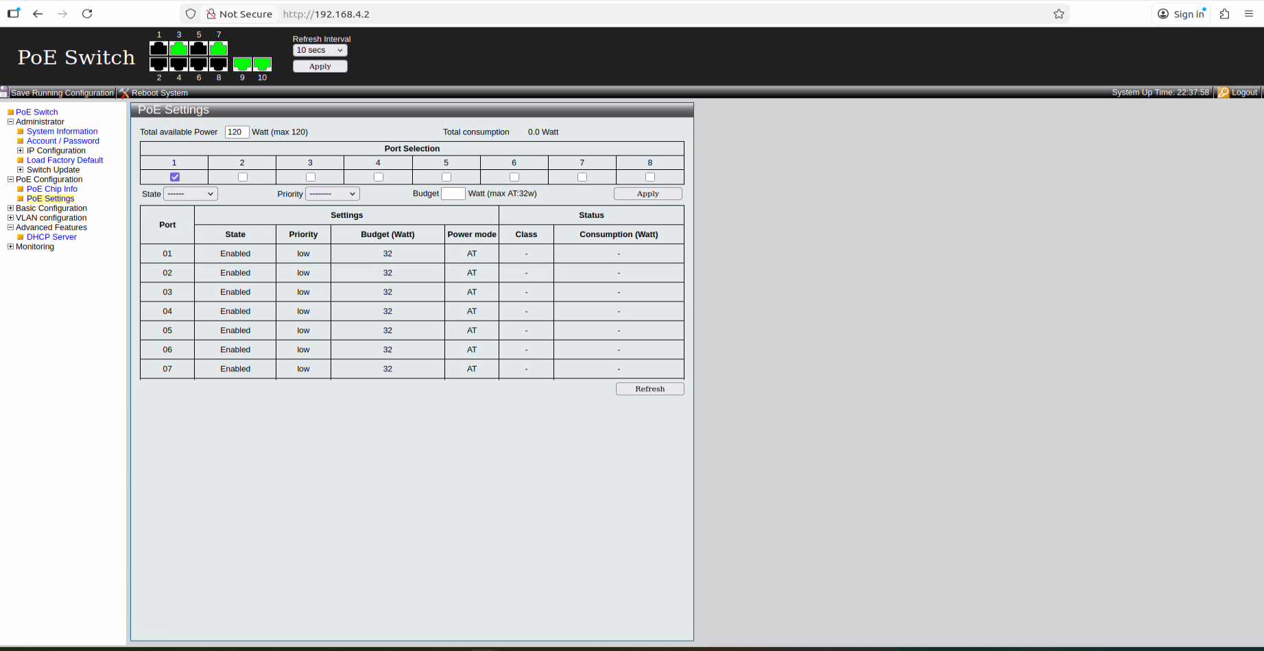
Initial State
→
PoE Disable / Power On
→
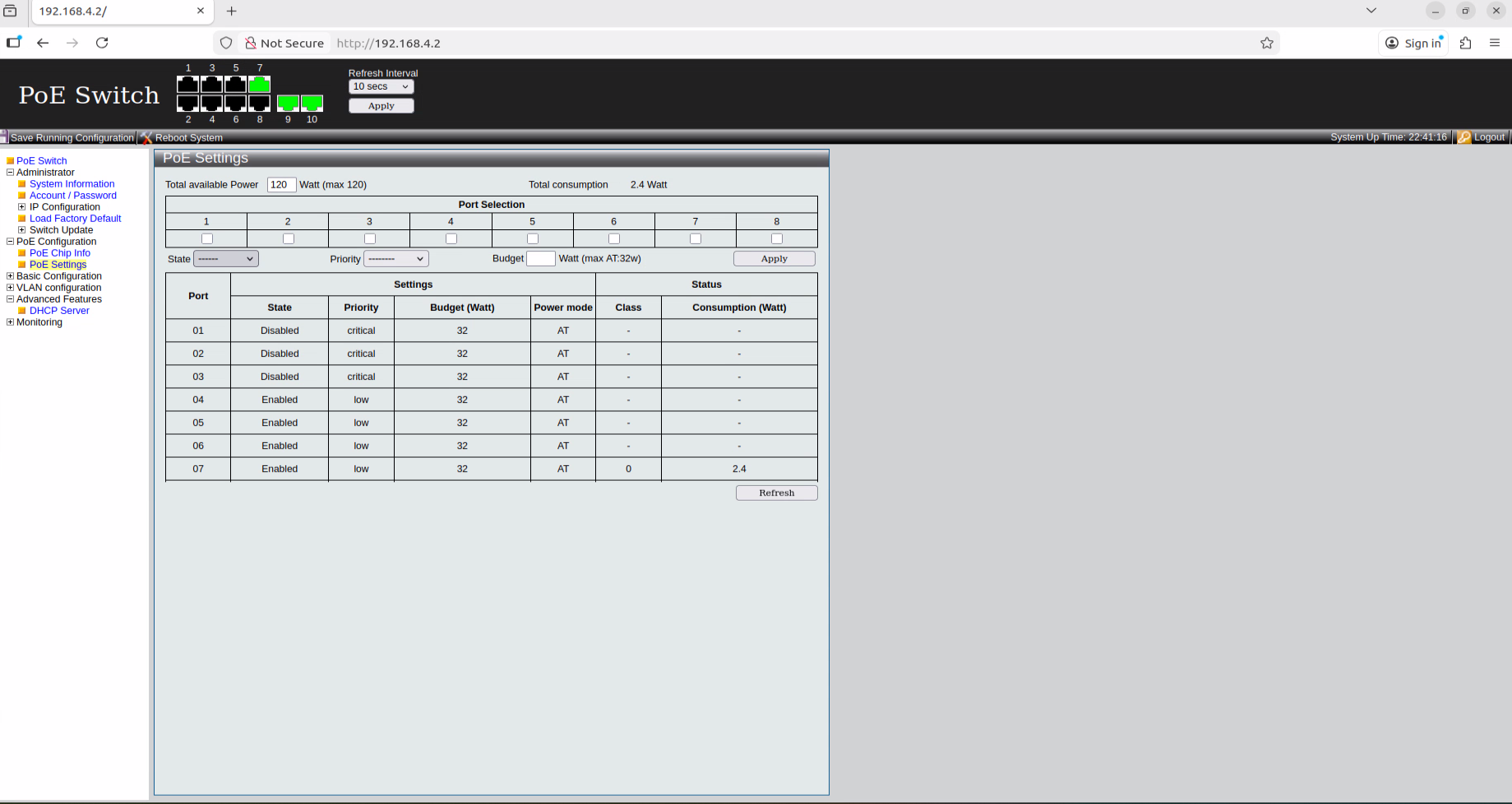
Power Cycling
Note: Use port cycling carefully to avoid unintended camera resets. Always verify that PoE devices are connected to the correct ports before applying changes.
Katana Additional IP Configuration (Linux GUI)
If you do not change the Katana Switch IP from default, or Switch IP is different to subnet from LAN you may need to assign an additional IP address to Katana's LAN interface using the Linux graphical user interface (GUI).
This allows Katana to communicate with both the existing network and the Katana switch.
** If Katana switch IP is changed to match the subnet of LAN network then this step is not required **.
This configuration is performed using the Linux graphical user interface. Menu names may vary slightly depending on the Linux distribution
To configure the IP addresses via the Linux GUI:
- Open Settings → Network.
- Select the wired connection associated with interface enp0s31f6.
- Click the Gear (⚙️) icon next to the connection.
- Go to the IPv4 tab.
- Change the Method to Manual.
- Add the primary IP address that belongs to the network you are currently connected to.
- Click Add to create a second IP entry for accessing the Katana switch.
Enter the following values for the additional IP address:
- IP Address: 192.168.50.xxx or on same subnet as katana Switch Ip if changes
- Netmask: 255.255.255.0 (or Prefix 24)
- Gateway: Not needed
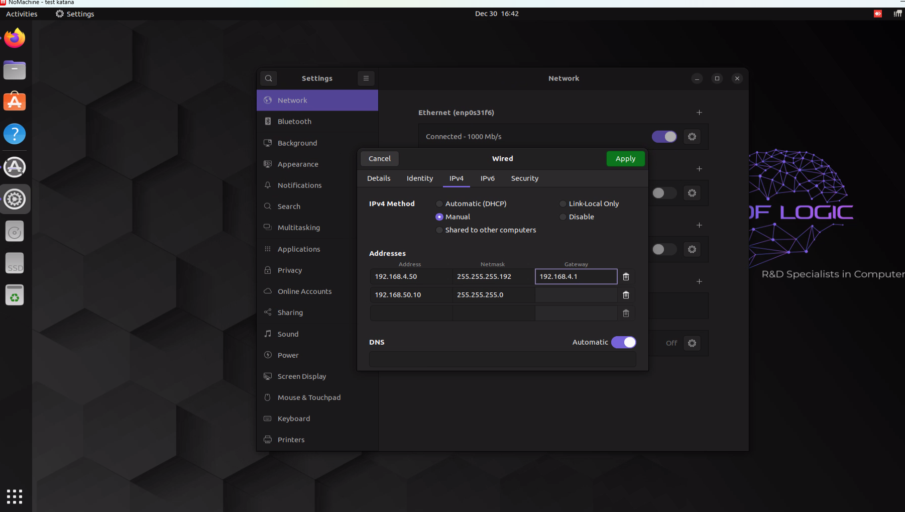
LINUX GUI MANUAL IP ADDRESS
Click Apply to save the configuration.
Important: Ensure that the Manual IP address does not conflict with any existing devices on the network.